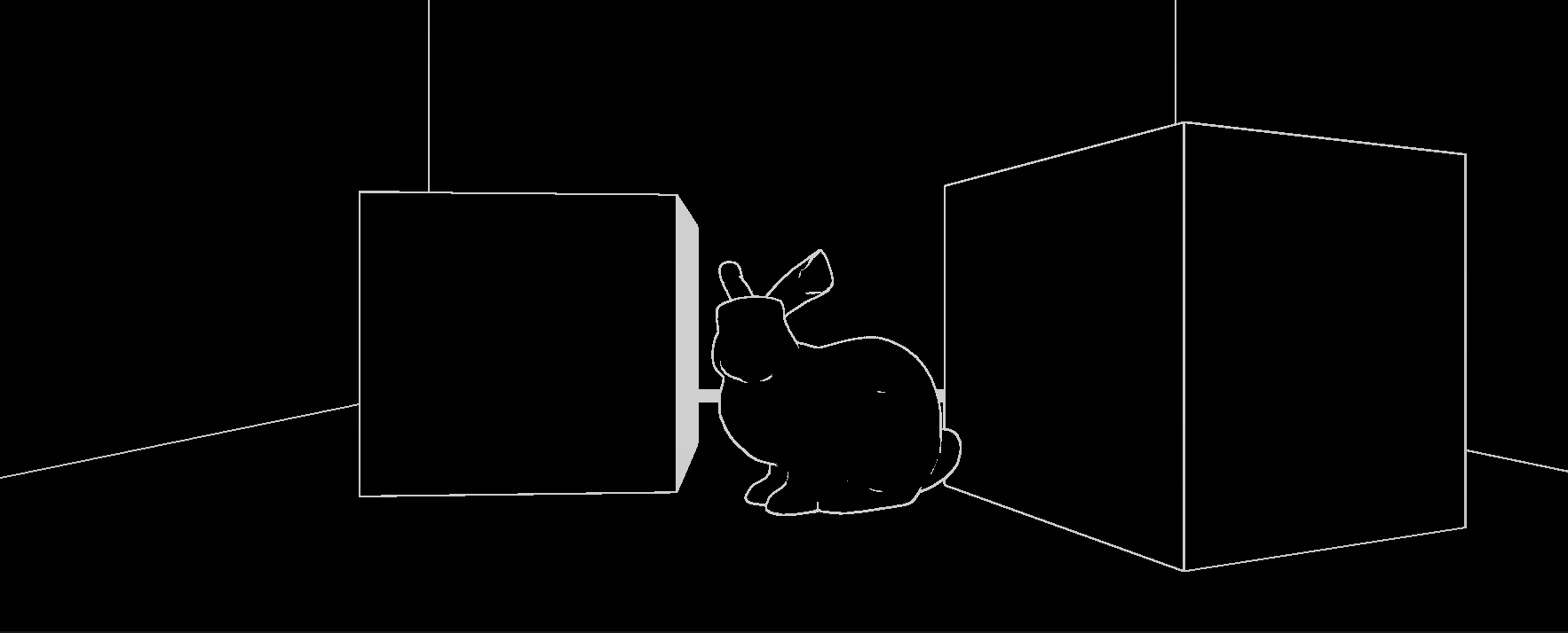
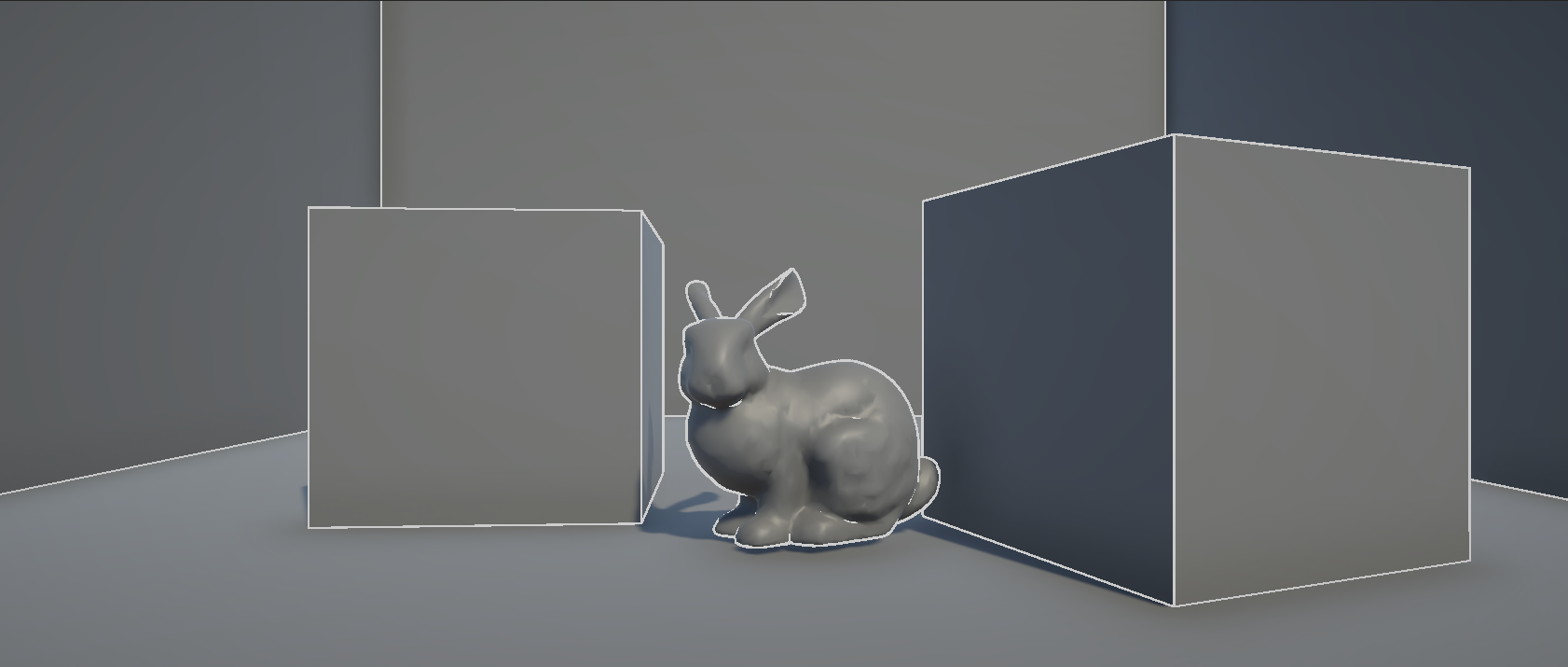
使用Renderer Feature能够真正发挥Unity通用渲染管线的功能,本文将使用一个Outline效果为例,通过自定义的Renderer Feature实现屏幕后处理。
代码地址:https://github.com/Li-Kira/CodeLib/tree/main/Unity/URP/PostProcess/Outline
Overview
在开始之前,我们需要设置好我们的项目。本文使用的Unity版本为2022.3.11,由于Unity Renderer Feature相关的代码一直在变动,比如Unity Renderer Feature中正逐渐使用RTHandle取代RenderTexture,Bliter取代Blit。本文使用到的技术随时可能会失效,但仍希望本文的内容能够给你带来启发。
本文包含以下内容,到第二部分结束你就可以实现一个基于屏幕的后处理效果,而第三部分的内容主要是探讨在不同图层下后处理效果的可见性。
- Renderer Feature
- Shader
- LayerMask(未完成)
Renderer Feature
我们需要实现以下脚本,并让他们能够在URP内一起工作:
- VolumeComponent:用来在Global Volume中通过控制面板参数来实现后处理效果的调整。
- RendererFeature: 向URP渲染器添加额外的渲染Pass, 让这些Pass能够在渲染器中执行。
- RenderPass:用来执行渲染相关的操作。
Scriptable Render Pipeline Settings
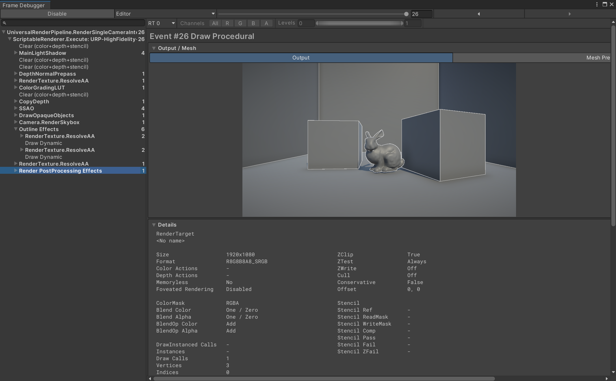
在开始代码之前,我们需要知道我们实现的效果会在渲染管线中的哪里被绘制,可以前往Window -> Analysis -> Frame Debugger,通过启动Frame Debugger我们可以看到一个渲染队列,我们之后实现的效果就会被加入这个队列中。
下图展示了在默认的URP-HighFidelity-Renderer渲染器下画面的绘制过程,它包含了多个用来渲染画面的Pass,这些Pass从上往下逐次绘制,而我们的Outline效果在Outline Effects这个Pass里面,由于我们将renderPassEvent`设置为BeforeRenderingPostProcessing,这个效果的绘制顺序被放在了URP内置的后处理效果之前。
为了将我们的Renderer Feature加入到这个渲染器中,我们可以到Projece Settings -> Graphics -> Scriptable Render Pipeline Settings中选择我们自定义的渲染器配置文件,或者使用URP内置的渲染器配置文件,在渲染器列表中我们可以看到这个配置文件使用的渲染器,如果是URP内置的渲染器配置文件,它使用的渲染器是URP-HighFidelity-Renderer,可以在项目文件中的Settings中找到。
在这个渲染器的面板下面点击Add Renderer Feature就能够将我们写好的Renderer Feature加入到渲染器中了。
Volume Component
为了能向Global Volume一样便利地调整后处理效果,我们需要编写这个脚本,它主要是用来声明各种参数,供Render Pass传递给Shader
下面这段代码包含了需要的参数,以及供Global Volume定位的路径。
1
2
3
4
5
6
7
8
9
10
11
12
13
14
15
16
17
| [Serializable]
[VolumeComponentMenuForRenderPipeline("Custom/Outline", typeof(UniversalRenderPipeline))]
public class OutlineEffectComponent : VolumeComponent, IPostProcessComponent
{
[Header("Edge Detection Settings")]
public ClampedFloatParameter scale = new ClampedFloatParameter(value: 0, min: 0, max: 5);
public ClampedFloatParameter depthThreshold = new ClampedFloatParameter(value: 20f, min: 0, max: 30, true);
public ClampedFloatParameter normalThreshold = new ClampedFloatParameter(value: 0.7f, min: 0, max: 2, true);
public ClampedFloatParameter depthNormalThreshold = new ClampedFloatParameter(value: 0.5f, min: 0, max: 1, true);
public ClampedFloatParameter depthNormalThresholdScale = new ClampedFloatParameter (value: 7, min: 0, max: 10, true);
[Header("Line Settings")]
public NoInterpColorParameter edgeColor = new NoInterpColorParameter(Color.white, true);
public bool IsActive() => true;
public bool IsTileCompatible() => true;
}
|
Renderer Feature
下面这段代码是从ScriptableRendererFeature中继承而来的,它需要重写Create和AddRenderPasses方法。
- Create:用来创建以及初始化相关的Pass,它在OnEnable阶段执行
- AddRenderPasses:用来将Pass加入到渲染队列中
了解了这些,剩下的代码就很简单了,无非是对参数的一些初始化,需要注意的是这里的材质使用CoreUtils.CreateEngineMaterial自动创建,在生命周期结束后需要被删除。
1
2
3
4
5
6
7
8
9
10
11
12
13
14
15
16
17
18
19
20
21
22
23
24
25
| [System.Serializable]
public class OutlinePostProcessRenderFeature : ScriptableRendererFeature
{
[SerializeField]
private Shader m_Shader;
private Material m_Material;
private OutlinePass m_outlinePass;
public override void Create()
{
m_Material = CoreUtils.CreateEngineMaterial(m_Shader);
m_outlinePass = new OutlinePass(m_Material);
}
public override void AddRenderPasses(ScriptableRenderer renderer, ref RenderingData renderingData)
{
renderer.EnqueuePass(m_outlinePass);
}
protected override void Dispose(bool disposing)
{
CoreUtils.Destroy(m_Material);
}
}
|
Render Pass
在Render Pass中,最重要的渲染事件发生在我们重写的Execute方法中,首先我们需要从Volume Stack中获取Volume Component相关的参数,然后将其传入到材质中,然后需要根据从相机获取的Render Texture将画面与Shader渲染的画面混合。
具体的实现代码如下:
1
2
3
4
5
6
7
8
9
10
11
12
13
14
15
16
17
18
19
20
21
22
23
24
25
26
27
28
29
30
31
32
33
34
35
36
37
38
39
40
41
42
43
44
45
46
47
48
49
50
51
52
53
54
55
56
57
58
59
60
61
62
63
64
65
66
67
68
69
70
71
72
| public class OutlinePass : ScriptableRenderPass
{
private RenderTargetIdentifier m_Source;
private RenderTargetIdentifier m_Destination;
private Material m_Material;
private OutlineEffectComponent m_OutlineEffect;
private readonly int temporaryRTId = Shader.PropertyToID("_TempRT");
public OutlinePass(Material OutlineMaterial, RenderQueueType renderQueueType, int layerMask)
{
renderPassEvent = RenderPassEvent.BeforeRenderingPostProcessing;
m_Material = OutlineMaterial;
}
public override void OnCameraSetup(CommandBuffer cmd, ref RenderingData renderingData)
{
RenderTextureDescriptor descriptor = renderingData.cameraData.cameraTargetDescriptor;
descriptor.depthBufferBits = 0;
m_Source = renderingData.cameraData.renderer.cameraColorTarget;
cmd.GetTemporaryRT(temporaryRTId, descriptor, FilterMode.Bilinear);
m_Destination = new RenderTargetIdentifier(temporaryRTId);
}
public override void Execute(ScriptableRenderContext context, ref RenderingData renderingData)
{
if (renderingData.cameraData.isSceneViewCamera)
return;
CommandBuffer cmd = CommandBufferPool.Get();
VolumeStack stack = VolumeManager.instance.stack;
m_OutlineEffect = stack.GetComponent<OutlineEffectComponent>();
using (new ProfilingScope(cmd, new ProfilingSampler("Outline Effects")))
{
Render(cmd, renderingData);
}
context.ExecuteCommandBuffer(cmd);
cmd.Clear();
CommandBufferPool.Release(cmd);
}
public void Render(CommandBuffer cmd, RenderingData renderingData, int pass = 0)
{
m_Material.SetFloat("_Scale", m_OutlineEffect.scale.value);
m_Material.SetFloat("_DepthThreshold", m_OutlineEffect.depthThreshold.value);
m_Material.SetFloat("_NormalThreshold", m_OutlineEffect.normalThreshold.value);
Matrix4x4 clipToView = GL.GetGPUProjectionMatrix(renderingData.cameraData.GetProjectionMatrix(), true).inverse;
m_Material.SetMatrix("_ClipToView", clipToView);
m_Material.SetFloat("_DepthNormalThreshold", m_OutlineEffect.depthNormalThreshold.value);
m_Material.SetFloat("_DepthNormalThresholdScale", m_OutlineEffect.depthNormalThresholdScale.value);
m_Material.SetColor("_EdgeColor", m_OutlineEffect.edgeColor.value);
Blit(cmd, m_Source, m_Destination, m_Material, pass);
Blit(cmd, m_Destination, m_Source);
}
public override void OnCameraCleanup(CommandBuffer cmd)
{
cmd.ReleaseTemporaryRT(temporaryRTId);
}
}
|
Shader
Shader的部分参考这篇文章:https://roystan.net/articles/outline-shader/
边缘检测
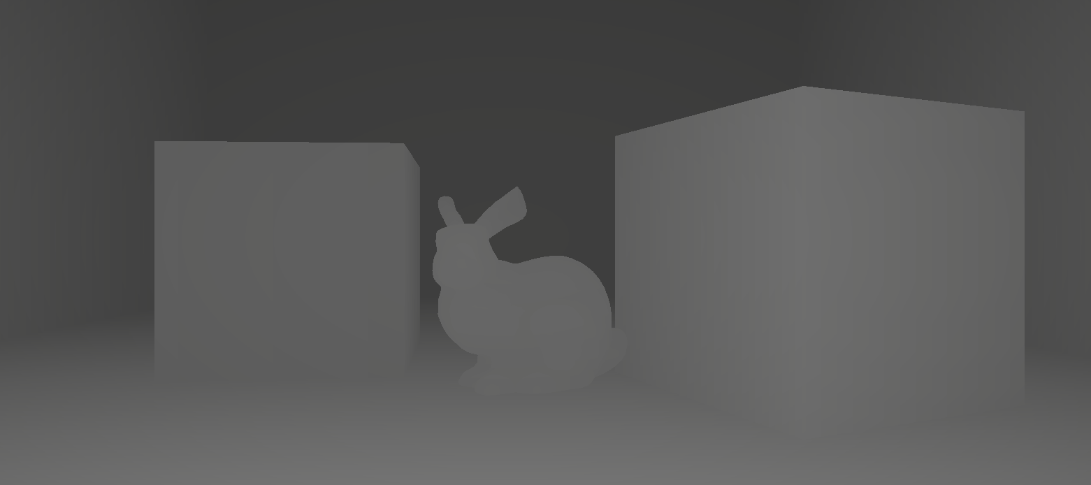
实现Outline的方法有很多,比如说法线外扩、使用Sobel算子对图像的边缘识别,这里使用的是基于深度和法线贴图的边缘识别。后两种方法的原理是通过判断颜色周围的差值,如果达到一点的阈值,那么就认为他们之间存在着一条边界线。在Shader中我们可以使用SAMPLE_DEPTH_TEXTURE这个宏函数获得深度图。
1
2
3
4
5
6
7
8
9
10
11
12
13
14
15
| float halfScaleFloor = floor(_Scale * 0.5);
float halfScaleCeil = ceil(_Scale * 0.5);
float2 bottomLeftUV = i.texcoord - float2(_MainTex_TexelSize.x, _MainTex_TexelSize.y) * halfScaleFloor;
float2 topRightUV = i.texcoord + float2(_MainTex_TexelSize.x, _MainTex_TexelSize.y) * halfScaleCeil;
float2 bottomRightUV = i.texcoord + float2(_MainTex_TexelSize.x * halfScaleCeil, -_MainTex_TexelSize.y * halfScaleFloor);
float2 topLeftUV = i.texcoord + float2(-_MainTex_TexelSize.x * halfScaleFloor, _MainTex_TexelSize.y * halfScaleCeil);
float depth0 = SAMPLE_DEPTH_TEXTURE(_CameraDepthTexture, sampler_CameraDepthTexture, bottomLeftUV).r;
float depth1 = SAMPLE_DEPTH_TEXTURE(_CameraDepthTexture, sampler_CameraDepthTexture, topRightUV).r;
float depth2 = SAMPLE_DEPTH_TEXTURE(_CameraDepthTexture, sampler_CameraDepthTexture, bottomRightUV).r;
float depth3 = SAMPLE_DEPTH_TEXTURE(_CameraDepthTexture, sampler_CameraDepthTexture, topLeftUV).r;
return depth0;
|
depthFiniteDifference0是检测到的边缘的一半,而 depthFiniteReference1是另一半,将他们结合起来能够得到我们需要的outline。
1
2
3
4
5
6
7
| float depthFiniteDifference0 = depth1 - depth0;
float depthFiniteDifference1 = depth3 - depth2;
float edgeDepth = sqrt(pow(depthFiniteDifference0, 2) + pow(depthFiniteDifference1, 2)) * 100;
edgeDepth = edgeDepth > depthThreshold ? 1 : 0;
return edgeDepth;
|
为了得到更清晰的边缘,我们设置一个阈值需要去掉不需要的部分:
1
2
| edgeDepth = edgeDepth > depthThreshold ? 1 : 0;
return edgeDepth;
|
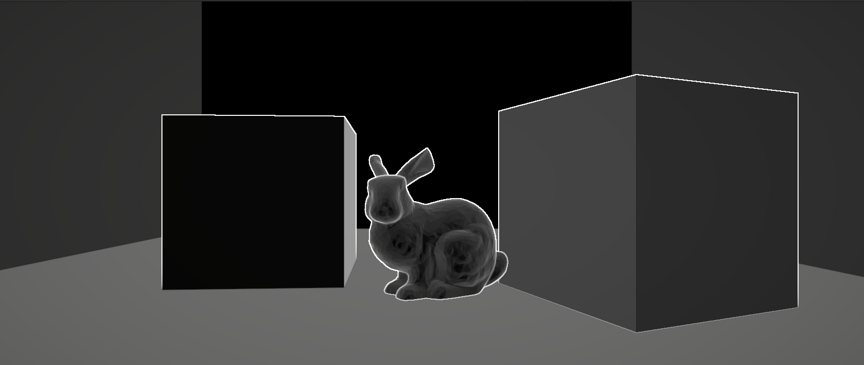
同理我们可以得到法线贴图,需要注意的是,我们得到的normalFiniteDifference是一个向量,要得到它的值需要让他自己对自己做一个点乘
1
2
3
4
5
6
7
8
9
10
11
|
float3 normal0 = SAMPLE_TEXTURE2D(_CameraNormalsTexture, sampler_CameraNormalsTexture, bottomLeftUV).rgb;
float3 normal1 = SAMPLE_TEXTURE2D(_CameraNormalsTexture, sampler_CameraNormalsTexture, topRightUV).rgb;
float3 normal2 = SAMPLE_TEXTURE2D(_CameraNormalsTexture, sampler_CameraNormalsTexture, bottomRightUV).rgb;
float3 normal3 = SAMPLE_TEXTURE2D(_CameraNormalsTexture, sampler_CameraNormalsTexture, topLeftUV).rgb;
float3 normalFiniteDifference0 = normal1 - normal0;
float3 normalFiniteDifference1 = normal3 - normal2;
float edgeNormal = sqrt(dot(normalFiniteDifference0, normalFiniteDifference0) + dot(normalFiniteDifference1, normalFiniteDifference1));
edgeNormal = edgeNormal > _NormalThreshold ? 1 : 0;
|
然后取他们之间的最大值,也就是都有边界的地方就能得到我们需要的outline,但是这个时候算法将一整片相近的地方都识别成了边缘,因为表面的倾斜程度越大,相邻像素的深度差就越大,这些表面上的大深度差导致我们的算法在它们上面检测到了边缘。因此我们需要通过计算视角方向进行矫正。
1
2
| float edge = max(edgeDepth, edgeNormal);
return edge;
|
矫正
我们从_CameraNormalsTexture采样的法线是在视图空间中的;由于这是我们想要比较的内容,我们还需要摄像机的视图方向也在视图空间中。由于我们正在使用屏幕空间着色器,可以轻松地从顶点位置计算裁剪空间中的视图方向。要将其转换为视图空间,我们将需要访问相机的裁剪到视图或逆投影矩阵。
通过C#脚本获取这个变换矩阵,然后通过Render Pass传递给Shader。
1
| Matrix4x4 clipToView = GL.GetGPUProjectionMatrix(context.camera.projectionMatrix, true).inverse;
|
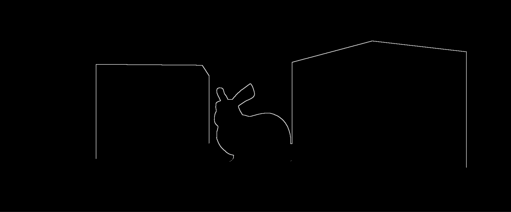
我们将根据相机的视图法线与表面法线之间的差异来调制depthThreshold,这样随着法线和相机之间的角度增加,点积的结果会变得更大。
由于depthThreshold随着角度的增加而变大,这时候只有真正的边界才能被当成边缘。
代码如下:
1
2
3
4
5
6
7
8
9
10
11
12
13
14
15
16
|
float3 viewNormal = normal0 * 2 - 1;
float NdotV = 1 - dot(viewNormal, -i.viewSpaceDir);
float normalThreshold01 = saturate((NdotV - _DepthNormalThreshold) / (1 - _DepthNormalThreshold));
float normalThreshold = normalThreshold01 * _DepthNormalThresholdScale + 1;
float depthThreshold = _DepthThreshold * depth0 * normalThreshold;
float edgeDepth = sqrt(pow(depthFiniteDifference0, 2) + pow(depthFiniteDifference1, 2)) * 100;
edgeDepth = edgeDepth > depthThreshold ? 1 : 0;
float edgeNormal = sqrt(dot(normalFiniteDifference0, normalFiniteDifference0) + dot(normalFiniteDifference1, normalFiniteDifference1));
edgeNormal = edgeNormal > _NormalThreshold ? 1 : 0;
float edge = max(edgeDepth, edgeNormal);
|
最后我们将边缘与原画面进行混合,得到最终的结果:
1
2
3
4
5
6
7
8
9
10
11
12
13
14
| float4 alphaBlend(float4 top, float4 bottom)
{
float3 color = (top.rgb * top.a) + (bottom.rgb * (1 - top.a));
float alpha = top.a + bottom.a * (1 - top.a);
return float4(color, alpha);
}
...
float4 color = SAMPLE_TEXTURE2D(_MainTex, sampler_MainTex, i.texcoord);
return alphaBlend(edgeColor, color);
|
常见问题解决
拓展阅读
Blit Usage
Outline Shader
Layer Mask